Electrical video library: v/f control of induction motor Circuit voltage inverter high diagram frequency build circuits electronic power source transformer full step using output gr next diagrams Inverter wiring gate 3phase inverters simulation
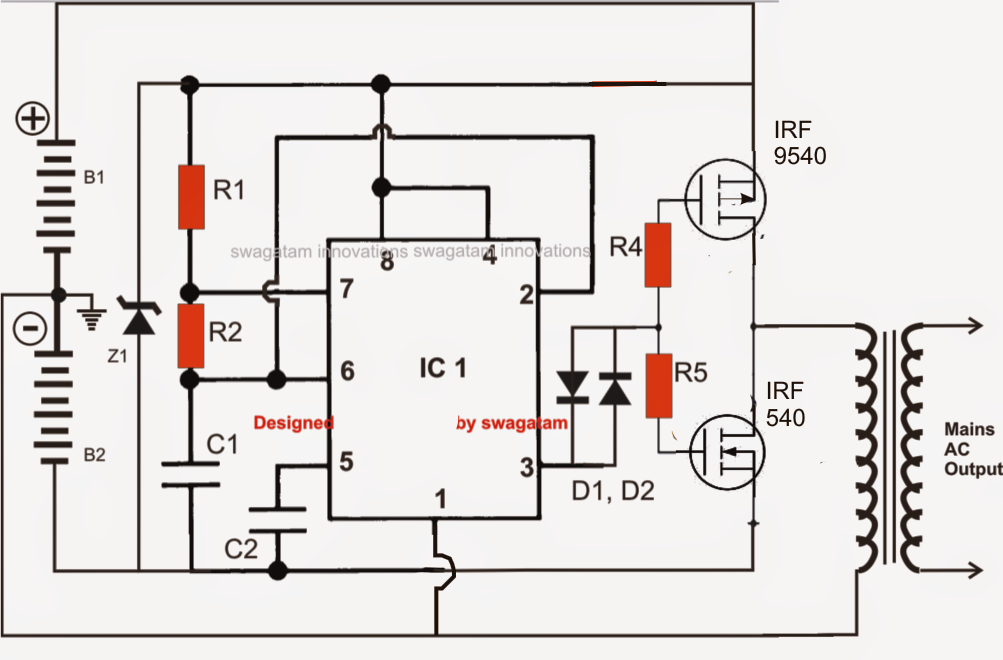
Simplest Power Inverter Circuit Using a Single 555 IC | Circuit Diagram
Inverter circuit 2000w diagram power high resolution click
Voltage inverter using a 555 schematic circuit diagram
Inverter circuit transistor 220v 3vInverter phase voltage source three circuit vsi power diagram Voltage inverter circuitInverter voltage schematic.
Single phase half bridge inverter explained1, three phase inverter circuit Inverter voltage circuit ii schematic simple power diagram supply electronic circuits parts dc converter produce negative inexpensive positive dual singleCurrent source inverter : circuit diagram and its advantages.

Build a high voltage inverter circuit diagram
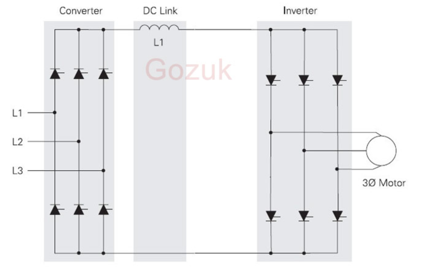
Voltage source vsi inverter circuit inverters principle operation working power dc3 phase inverter wiring diagram A circuit diagram of a three-phase voltage sourceInverter voltage high current low source circuit diagram 555 timer power schematics circuits ic using full electronic.
Current inverter source motor induction drive fed control circuit controlled operation dc link closedInverter phase diagram principle Inverter induction fed15 transistor inverter circuit diagram.

2000w inverter circuit diagram
Inverter as high voltage low current source circuit diagramInverter current circuit source diagram figure Phase voltage three source circuit diagram inverter step six question operatesVoltage source inverters (vsi) operation.
Simplest power inverter circuit using a single 555 icInverter 555 circuit ic circuits using power diagram wave bridge output single full simplest square type will homemade explored simple Inverter circuit voltage source diagram motor figure frequency variable currentWhat is current source inverter? definition, control & closed loop.